![]() 27 Oct 2016, 08:52
27 Oct 2016, 08:52
Hello:
For a history on the clock check out the following links. This was a very important step in Quartz technology and is the predecessor of the Astron:
http://global.epson.com/company/corporate_history/milestone_products/02_qc-951.html
http://global.epson.com/company/corporate_history/milestone_products/pdf/02_qc-951.pdf
http://forum.tz-uk.com/showthread.php?201397-Marine-Chronometers-Seiko-QM-10-and-Seiko-951-II
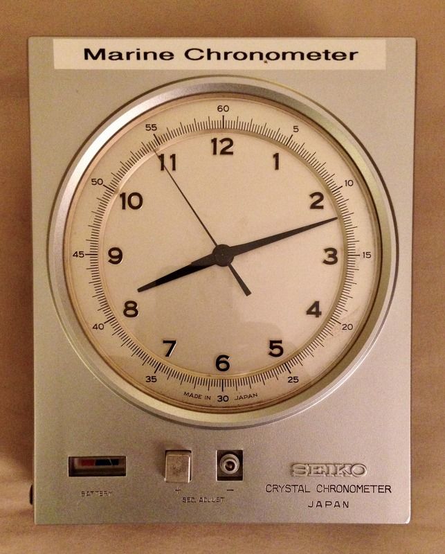
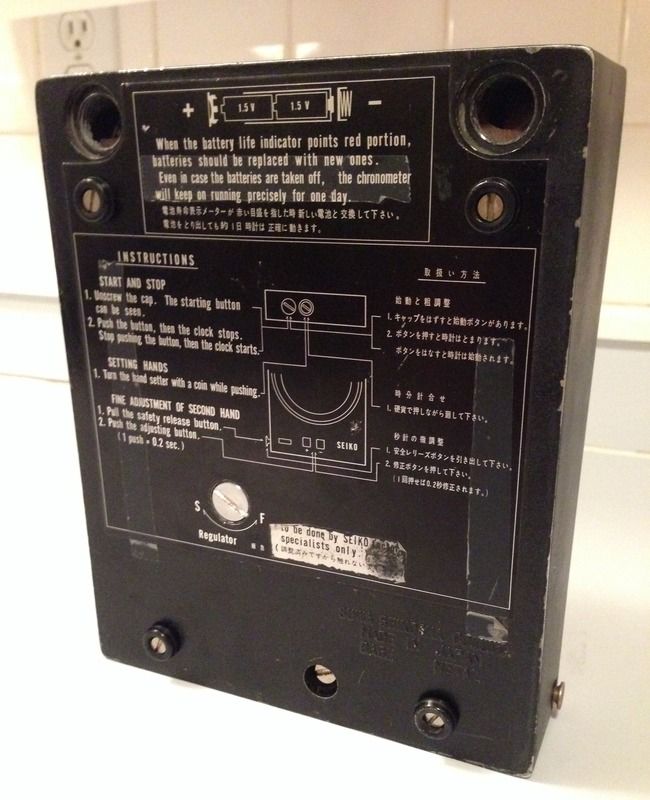
The clock arrived in non-working 'untested condition'. We all know what 'untested means ! It was mentioned that corrosion existed due to battery leakage of the main D cells. As it turned out, even if the D cells were installed this unit was a non-worker!
After researching the web and Watchuseek I found a user manual (the service manual is out there somewhere and is 200 pages!) and a few articles describing the history and some mechanical/electronic aspects of the clock. So armed with a tool kit and some rudimentary electronic testing I opened it up and found that someone had attempted repairs, lost screws and replaced the standby battery cells with alkaline AG13 with a poor solder job. Corrosion from the D cells had crept along the ground wire oxidizing it. The battery tube internal contact was corroded to a non conductive state. Two red wires were weakened by clumsy hands during a repair. Many weakened solder joints due to oxidation. This clock came from a ship salvage.
I played around, testing the continuity of the clock and managed to get it working with jumpers to the installed power supply circuit. However, to fully test and repair I knew I had to remove everything from the case. That led to a surprise, later on that.
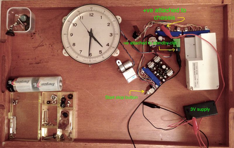
1) here we see the entire circuit and clock removed from the top and bottom shell. The power is supplied by two AA cells and attached directly to the -ve and +ve wires. The blue sections are the sockets that receive the various circuit boards.
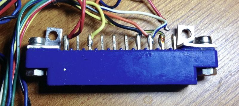
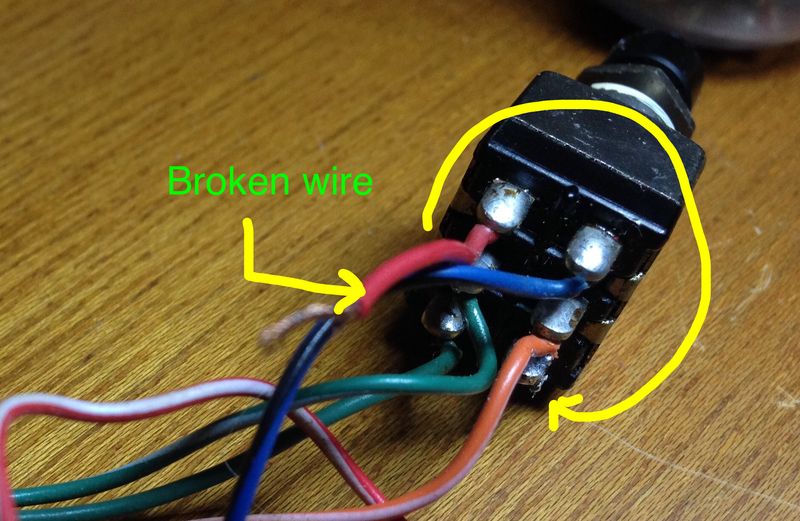
2) these photos are useful as a colour coded guide to resoldering broken wires. As the wires oxidize they become fragile as seen in photos 3 and 4. Remember, photos are your friend.
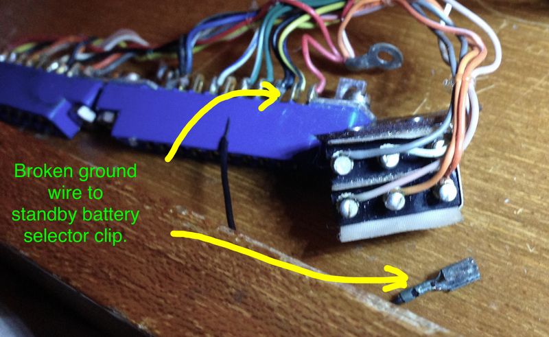
3a) the -ve or ground wire which attaches to the standby battery switching selector was severely oxidized and fell away from its solder joint.
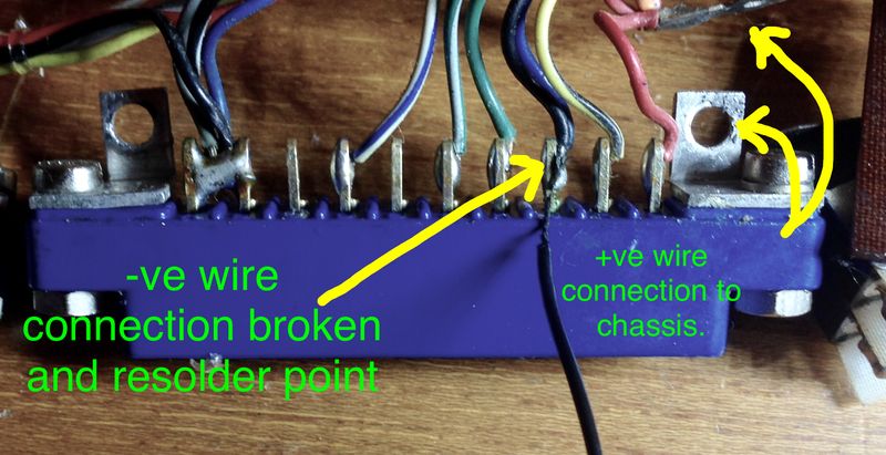
3b) you can see the clip end of the black wire in the lower right. It too was severely oxidized and needed mechanical and acid wash to receive solder and a new wire to complete the circuit.
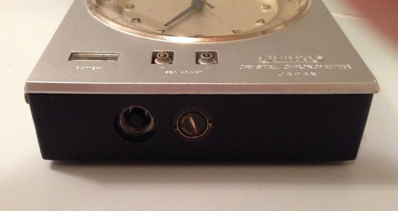
4) this is the start/stop push button and two wires separated from their respective solder points. All the wires that separated due to oxidation were replaced, three in all.
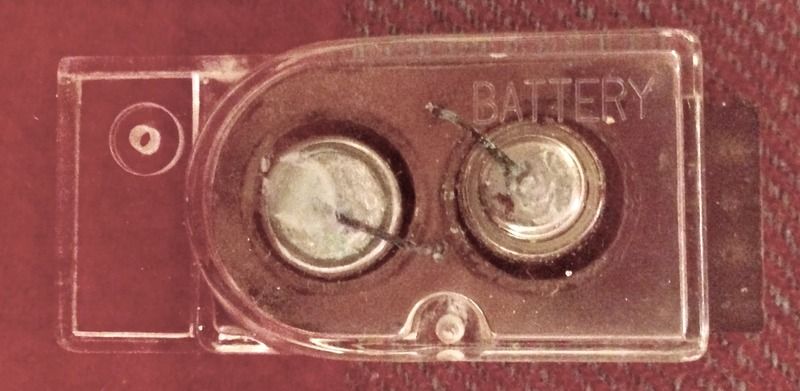
5a) the standby batteries with the bad solder job. Were these originally NiCd on a trickle charge circuit? I still have to test the circuit to see if there is current supplied to the standby battery circuit board. If no current then these should be standard silver oxide (alkalines in the day).
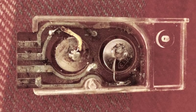
5b) the obverse view. I removed the batteries and cleaned up the circuit board so that new cells could be soldered in. Will do that when I am sure of which type they should be.
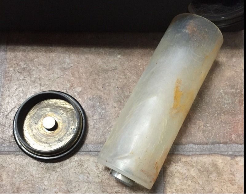
6a) next we move on to D cell plastic tube. The tube is required due to the length the internal/external contact adds to the overall length of the two D cells and contact. The batteries when inserted in the tube and then into the case receptacle pushes the standby battery selector switch open causing the power to be drawn from the D cells. When the cells are removed a spring at the base of the battery receptacle inside the cabinet closes the circuit transferring the power supply to the internal button backup cells. Here is what the battery cover and tube looked like prior to cleaning.
6b). The contact at the base of the tube inside was black with a thick layer of non conducting corrosion. Night in acid did not remove it. I had to physically remove it from the base of the plastic tube. Then grind away the corrosion to expose the brass contact. Then reinstall it back into the tube base.
6c). External contact.
6d). Tube ready for action.
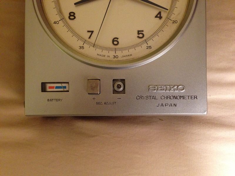
7a). The top bezel is brass or pot steel plated in chrome? Mine was very pitted and I may send it out for plating in the future. However a cleaning and a few coats of silver paint sufficed. The engraved script will be filled in with a black paint to emulate the original finish. Unfortunately my unit only came with one corrector button. I will fabricated one to match. The bottom shell was sanded and feathered at the paint chips and nicks then painted flat black.
7b)
7c)
And here is the surprise, the initial testing involved the clock circuits in situ in the case. All connectors attached with new screws replacing the missing ones. The clock functioned perfectly! I then removed the entire clock circuitry from the case (figure 1). New wires installed and soldering work completed. I then disassembled th 19 jewel movement, then cleaned and lubricated and reassembled the movement. I then rigged it externally as seen in figure one. Then I went about cleaning the top and bottom shells, glass and seals.
I returned to the clock which was functioning only to find it was running 4 seconds fast per minute! Well I was stumped. Did I mess the movement up when I disassembled it? Did the lube affect it? What a disappointment. I disassembled the movement again and reassembled, no change, 4 seconds per minute fast!!!
I decided, while waiting for some idea to come to me, to reassemble the clock inside the case while I pondered the predicament. To my surprise the clocks rate was perfect again. Removing it from the case caused it to repeat the fast rate. Reinstalling it caused the rate to return to normal. I can only suggest that there is a circuit that relies on a contact via the blue sockets (which one?) and it's securing screw to the chassis to help regulate the movement. The chassis is a positive chassis as the D cell positive end is contacted directly to the chassis (bottom shell). All the blue sockets are attached to the bottom shell via metal washers and screws.
It would be interesting to find an actual service manual to track down the electronics behind this. Suffice to say, don't time the circuit outside the chassis!
I have some finishing work on the case, new corrector push button to fabricate or secure and the clock will be done!
hope you enjoyed this, I will post some more pictures when fully completed.
Geoff
Running for three days now and spot on to my HeathKit GC-1000.
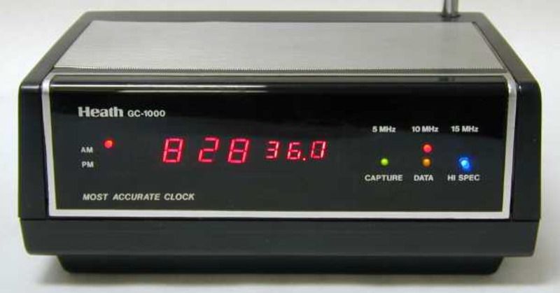
Picture borrowed from: http://www.nixie.dk/~jthomas/gc1000.html
For a history on the clock check out the following links. This was a very important step in Quartz technology and is the predecessor of the Astron:
http://global.epson.com/company/corporate_history/milestone_products/02_qc-951.html
http://global.epson.com/company/corporate_history/milestone_products/pdf/02_qc-951.pdf
http://forum.tz-uk.com/showthread.php?201397-Marine-Chronometers-Seiko-QM-10-and-Seiko-951-II
The clock arrived in non-working 'untested condition'. We all know what 'untested means ! It was mentioned that corrosion existed due to battery leakage of the main D cells. As it turned out, even if the D cells were installed this unit was a non-worker!
After researching the web and Watchuseek I found a user manual (the service manual is out there somewhere and is 200 pages!) and a few articles describing the history and some mechanical/electronic aspects of the clock. So armed with a tool kit and some rudimentary electronic testing I opened it up and found that someone had attempted repairs, lost screws and replaced the standby battery cells with alkaline AG13 with a poor solder job. Corrosion from the D cells had crept along the ground wire oxidizing it. The battery tube internal contact was corroded to a non conductive state. Two red wires were weakened by clumsy hands during a repair. Many weakened solder joints due to oxidation. This clock came from a ship salvage.
I played around, testing the continuity of the clock and managed to get it working with jumpers to the installed power supply circuit. However, to fully test and repair I knew I had to remove everything from the case. That led to a surprise, later on that.
1) here we see the entire circuit and clock removed from the top and bottom shell. The power is supplied by two AA cells and attached directly to the -ve and +ve wires. The blue sections are the sockets that receive the various circuit boards.
2) these photos are useful as a colour coded guide to resoldering broken wires. As the wires oxidize they become fragile as seen in photos 3 and 4. Remember, photos are your friend.
3a) the -ve or ground wire which attaches to the standby battery switching selector was severely oxidized and fell away from its solder joint.
3b) you can see the clip end of the black wire in the lower right. It too was severely oxidized and needed mechanical and acid wash to receive solder and a new wire to complete the circuit.
4) this is the start/stop push button and two wires separated from their respective solder points. All the wires that separated due to oxidation were replaced, three in all.
5a) the standby batteries with the bad solder job. Were these originally NiCd on a trickle charge circuit? I still have to test the circuit to see if there is current supplied to the standby battery circuit board. If no current then these should be standard silver oxide (alkalines in the day).
5b) the obverse view. I removed the batteries and cleaned up the circuit board so that new cells could be soldered in. Will do that when I am sure of which type they should be.
6a) next we move on to D cell plastic tube. The tube is required due to the length the internal/external contact adds to the overall length of the two D cells and contact. The batteries when inserted in the tube and then into the case receptacle pushes the standby battery selector switch open causing the power to be drawn from the D cells. When the cells are removed a spring at the base of the battery receptacle inside the cabinet closes the circuit transferring the power supply to the internal button backup cells. Here is what the battery cover and tube looked like prior to cleaning.
6b). The contact at the base of the tube inside was black with a thick layer of non conducting corrosion. Night in acid did not remove it. I had to physically remove it from the base of the plastic tube. Then grind away the corrosion to expose the brass contact. Then reinstall it back into the tube base.
6c). External contact.
6d). Tube ready for action.
7a). The top bezel is brass or pot steel plated in chrome? Mine was very pitted and I may send it out for plating in the future. However a cleaning and a few coats of silver paint sufficed. The engraved script will be filled in with a black paint to emulate the original finish. Unfortunately my unit only came with one corrector button. I will fabricated one to match. The bottom shell was sanded and feathered at the paint chips and nicks then painted flat black.
7b)
7c)
And here is the surprise, the initial testing involved the clock circuits in situ in the case. All connectors attached with new screws replacing the missing ones. The clock functioned perfectly! I then removed the entire clock circuitry from the case (figure 1). New wires installed and soldering work completed. I then disassembled th 19 jewel movement, then cleaned and lubricated and reassembled the movement. I then rigged it externally as seen in figure one. Then I went about cleaning the top and bottom shells, glass and seals.
I returned to the clock which was functioning only to find it was running 4 seconds fast per minute! Well I was stumped. Did I mess the movement up when I disassembled it? Did the lube affect it? What a disappointment. I disassembled the movement again and reassembled, no change, 4 seconds per minute fast!!!
I decided, while waiting for some idea to come to me, to reassemble the clock inside the case while I pondered the predicament. To my surprise the clocks rate was perfect again. Removing it from the case caused it to repeat the fast rate. Reinstalling it caused the rate to return to normal. I can only suggest that there is a circuit that relies on a contact via the blue sockets (which one?) and it's securing screw to the chassis to help regulate the movement. The chassis is a positive chassis as the D cell positive end is contacted directly to the chassis (bottom shell). All the blue sockets are attached to the bottom shell via metal washers and screws.
It would be interesting to find an actual service manual to track down the electronics behind this. Suffice to say, don't time the circuit outside the chassis!
I have some finishing work on the case, new corrector push button to fabricate or secure and the clock will be done!
hope you enjoyed this, I will post some more pictures when fully completed.
Geoff
Running for three days now and spot on to my HeathKit GC-1000.
Picture borrowed from: http://www.nixie.dk/~jthomas/gc1000.html