

![]() 21 Nov 2019, 03:20
21 Nov 2019, 03:20
Also known as a WITSCHI Q TEST 4100.
Got this off Ebay for $400 with the displays working but in untested condition. No guarantees on accuracy or if fully functional. Well I love a puzzle and knowing the displays were okay I thought my chances of getting this fully functional would be 50/50.
So it arrived well packaged and shipped from Europe.
I noticed they writing in places on the main bezel for the supply voltage test section was corroded and missing. Case was very dirty along with the wood case. The wiring was for 220 volts but is switchable to 120 volts and with a European to American plug converter.
Plugged it in and noticed the on off switch was hooked up backwards, that is the off was on and the on was off! This told me that someone had been inside the tester other then the makers.
When opened I noticed some wires were broken from their soldered positions. The timing display function for 18000 and 26600 mechanical, 32kHz and Accutron tuning fork was displaying correct daily and monthly errors, more on that later. The voltage testing and internal voltage supply for testing were non functional (the side with broken wires).
The mirror was loose and foam for the mirror was decomposed and also the white collar was completely missing on the test side of the checker. The white collar reflects light illuminating the under side (display side) of the module under test.
Both LED red filters were loose and came off when the case was disassembled.
So problem when I received it:
1) wires not connected internally.
2) loose ICs (they are all plug into sockets, amazing).
3) mirror on testing side loose
4) foam underlay for mirror which pushes up and into the large PCA decomposed.
5) collar which surrounds the internal mirrored testing side missing.
6) on off switch hooked up backwards.
7) whether correct or not the electrolytic are all 33 years of age so they may be suspect.
8) NO MANUAL or INSTRUCTIONS (any help here would be appreciated).
9) wood cover stained and finish deteriorated.
10) metal bezel had corrosion on surface as though acid had been leaked onto it.
11) supply voltage writing missing due to the corrosion.
12) red led filters both loose or separated from the upper face plate.
13) missing probes for the test side of the checker.
What I did:
Electronics
1) disassembled components.
2) replaced all capacitors with like capacitance and 5% tolerance.
3) resoldered broken wires to correct probe locations.
4) upper PCA which contains the LED modules.
- Removed LED blocks and cleaned all push button contacts as well as battery knob pot and PCA.
5) main PCA cleaned and all ICs reseated after being treated with detox-it electronic preserver.
6) cleaned the sensor pads being REALLY careful about the wiring under the detector PCA.
Case:
1) lightly sanded wood and lacquered with satin finish.
2) cleaned corrosion off the aluminum bezel and cleaned up the engraved supply voltage writing.
- Then filled in the writing.
- lacquered the metal bezel upper and lower in satin lacquer.
3) polished and reattached the LED red lenses.
4) cleaned mirror and mounted on new foam.
5) found a spray paint cap of the perfect size and colour to replace the missing collar around the mirror.
- Cut to size and mounted it.
6) added rubber feet to base.
7) will remake the probes for the test side and already secured test probes.
So the BEFORE pictures:
As it arrived EXTERNAL:

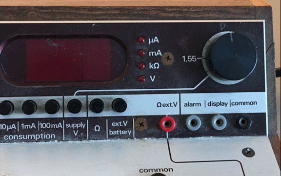
Upper right closeup:
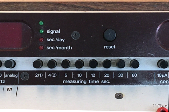
Upper center closeup:
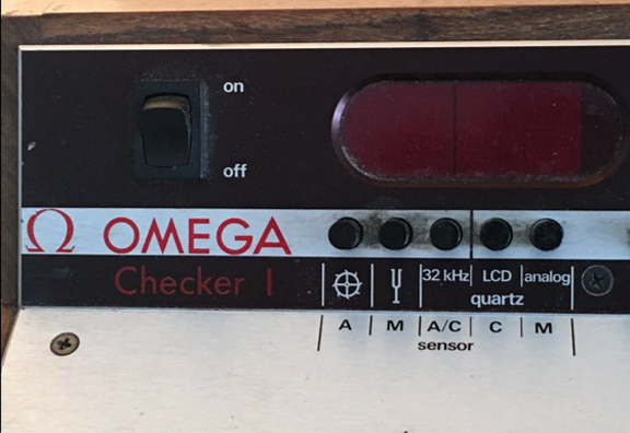
Upper left closeup:
Over view: note the white collar on the right side surrounding the mirror on the testing side is missing.
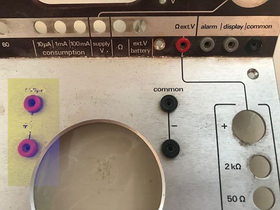
Damage to the aluminum bezel at the supply voltage side of the checker (yellow box):
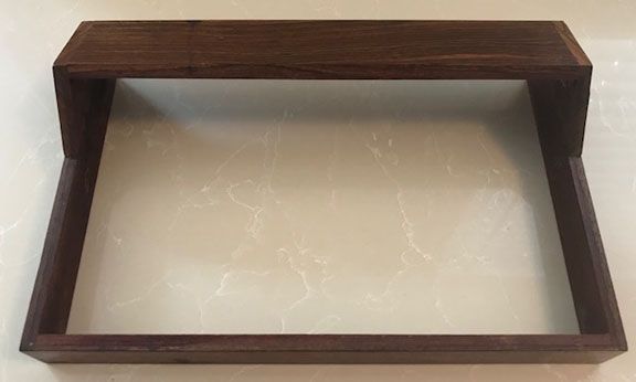
Wood with damaged finish:
As it arrived INTERNAL:
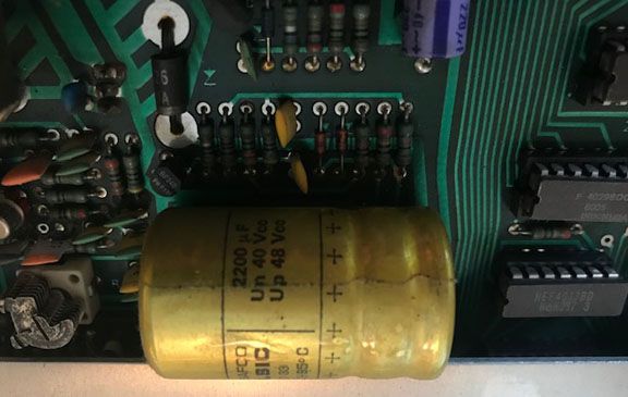
Capacitor on main PCA (replaced).
Other parts of the main PCA with capacitors and dirt on PCA.
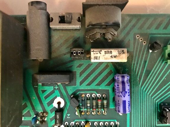
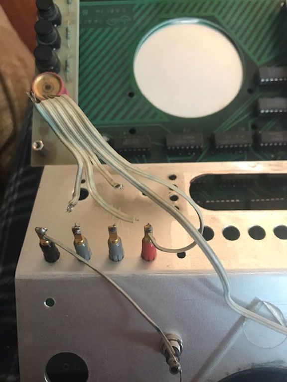
Broken wires to testing side of the checker:
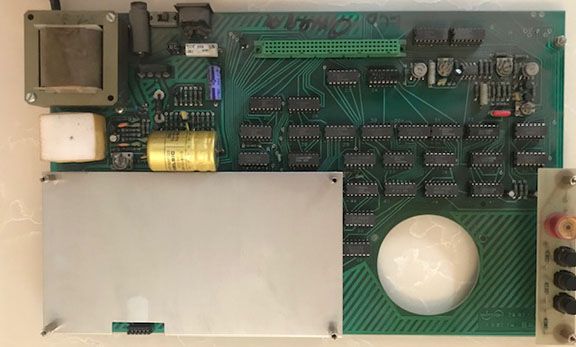
Main PCA with shielding for smaller sensor pad PCA;
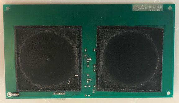
Sensor PCA pads obverse side:
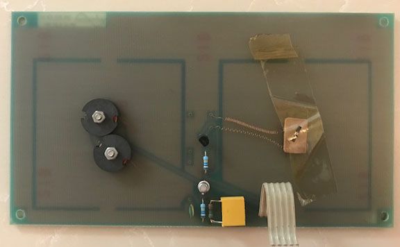
Sensor PCA reverse side:
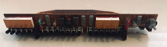
Upper display PCA with push buttons all cleaned:
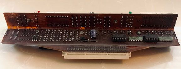
Reverse of the upper display:
AND NOW THE REVEAL:
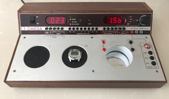
The overview with lacquered wood and bezel. Supply voltage writing redone. All probe receptacles removed, sanded and polished then reinserted.
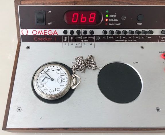
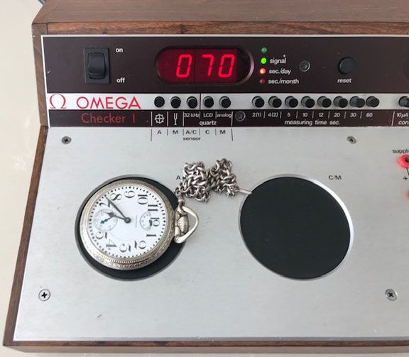
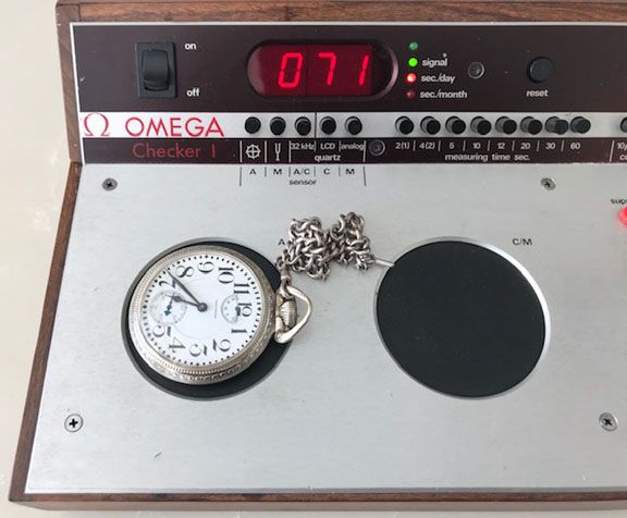
Three views of the pocket watch (18000bph) with the seconds per day displayed. You will notice the balance wheel button (far left
is selected) as is the 60 second sampling button. Also note the green signal led (which beats in relation to the watch beat) as well as the red led indicating seconds per day:
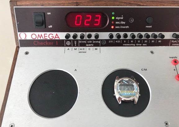
The LCD push button is selected with green signal and red seconds per month now indicated. Sampling time is 5 seconds:
Voltage of a battery under test, the EXT V push button is selected:
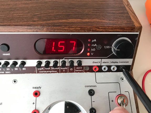
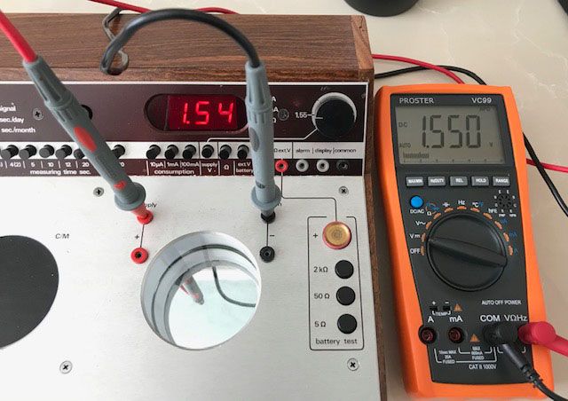
Internal supply voltage being tested for accuracy. Output is being tested by my multimeters. Note the selector knob is abeam the 1.55 volt indicator, not bad accuracy! The SUPPLY V push button is selected:
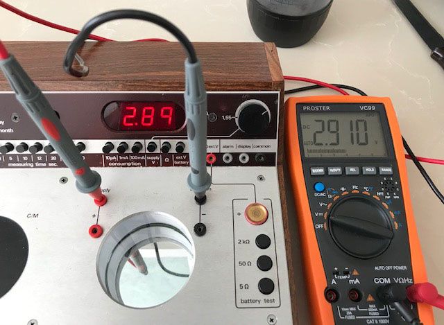
Here the voltage knob is selected to the highest value, almost 3 volts. These two voltages and all between are typical LCD and LED voltage requirements.
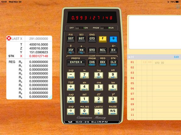
Here is the accuracy of the voltage measurements:
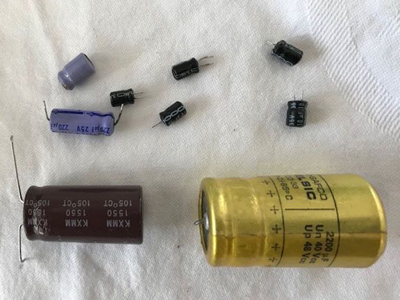
And the capacitors removed:
The missing probes, which I will be making later, would connect to the module + and - testing points. The module would be upside down and the display would be visible in the mirror.
There is an alarm button as well as a display button, again I need a manual to check these for functionality.
So I think I have it working. The tested seconds per day and seconds per month in the above examples check well with the watches actual performance. I also tested a Bulova Accutron, Omega 300 hertz and my 2.4 analog Omega Marine Master all check. The Omega Marine Master clocked in at 1 second per month on the tester and that coincides with its actual rate!
The quartz watches are divided into 32kHz, LCD and analog. The analog was used for the Marine Master so I guess it automatically detects the rates. Again I need the manual to determine what is what.
Hope you enjoyed the posting, I will do a YouTube video with various aspects of its capabilities demonstrated.
Best regards,
Geoff
Got this off Ebay for $400 with the displays working but in untested condition. No guarantees on accuracy or if fully functional. Well I love a puzzle and knowing the displays were okay I thought my chances of getting this fully functional would be 50/50.
So it arrived well packaged and shipped from Europe.
I noticed they writing in places on the main bezel for the supply voltage test section was corroded and missing. Case was very dirty along with the wood case. The wiring was for 220 volts but is switchable to 120 volts and with a European to American plug converter.
Plugged it in and noticed the on off switch was hooked up backwards, that is the off was on and the on was off! This told me that someone had been inside the tester other then the makers.
When opened I noticed some wires were broken from their soldered positions. The timing display function for 18000 and 26600 mechanical, 32kHz and Accutron tuning fork was displaying correct daily and monthly errors, more on that later. The voltage testing and internal voltage supply for testing were non functional (the side with broken wires).
The mirror was loose and foam for the mirror was decomposed and also the white collar was completely missing on the test side of the checker. The white collar reflects light illuminating the under side (display side) of the module under test.
Both LED red filters were loose and came off when the case was disassembled.
So problem when I received it:
1) wires not connected internally.
2) loose ICs (they are all plug into sockets, amazing).
3) mirror on testing side loose
4) foam underlay for mirror which pushes up and into the large PCA decomposed.
5) collar which surrounds the internal mirrored testing side missing.
6) on off switch hooked up backwards.
7) whether correct or not the electrolytic are all 33 years of age so they may be suspect.
8) NO MANUAL or INSTRUCTIONS (any help here would be appreciated).
9) wood cover stained and finish deteriorated.
10) metal bezel had corrosion on surface as though acid had been leaked onto it.
11) supply voltage writing missing due to the corrosion.
12) red led filters both loose or separated from the upper face plate.
13) missing probes for the test side of the checker.
What I did:
Electronics
1) disassembled components.
2) replaced all capacitors with like capacitance and 5% tolerance.
3) resoldered broken wires to correct probe locations.
4) upper PCA which contains the LED modules.
- Removed LED blocks and cleaned all push button contacts as well as battery knob pot and PCA.
5) main PCA cleaned and all ICs reseated after being treated with detox-it electronic preserver.
6) cleaned the sensor pads being REALLY careful about the wiring under the detector PCA.
Case:
1) lightly sanded wood and lacquered with satin finish.
2) cleaned corrosion off the aluminum bezel and cleaned up the engraved supply voltage writing.
- Then filled in the writing.
- lacquered the metal bezel upper and lower in satin lacquer.
3) polished and reattached the LED red lenses.
4) cleaned mirror and mounted on new foam.
5) found a spray paint cap of the perfect size and colour to replace the missing collar around the mirror.
- Cut to size and mounted it.
6) added rubber feet to base.
7) will remake the probes for the test side and already secured test probes.
So the BEFORE pictures:
As it arrived EXTERNAL:
Upper right closeup:
Upper center closeup:
Upper left closeup:
Over view: note the white collar on the right side surrounding the mirror on the testing side is missing.
Damage to the aluminum bezel at the supply voltage side of the checker (yellow box):
Wood with damaged finish:
As it arrived INTERNAL:
Capacitor on main PCA (replaced).
Other parts of the main PCA with capacitors and dirt on PCA.
Broken wires to testing side of the checker:
Main PCA with shielding for smaller sensor pad PCA;
Sensor PCA pads obverse side:
Sensor PCA reverse side:
Upper display PCA with push buttons all cleaned:
Reverse of the upper display:
AND NOW THE REVEAL:
The overview with lacquered wood and bezel. Supply voltage writing redone. All probe receptacles removed, sanded and polished then reinserted.
Three views of the pocket watch (18000bph) with the seconds per day displayed. You will notice the balance wheel button (far left
is selected) as is the 60 second sampling button. Also note the green signal led (which beats in relation to the watch beat) as well as the red led indicating seconds per day:
The LCD push button is selected with green signal and red seconds per month now indicated. Sampling time is 5 seconds:
Voltage of a battery under test, the EXT V push button is selected:
Internal supply voltage being tested for accuracy. Output is being tested by my multimeters. Note the selector knob is abeam the 1.55 volt indicator, not bad accuracy! The SUPPLY V push button is selected:
Here the voltage knob is selected to the highest value, almost 3 volts. These two voltages and all between are typical LCD and LED voltage requirements.
Here is the accuracy of the voltage measurements:
And the capacitors removed:
The missing probes, which I will be making later, would connect to the module + and - testing points. The module would be upside down and the display would be visible in the mirror.
There is an alarm button as well as a display button, again I need a manual to check these for functionality.
So I think I have it working. The tested seconds per day and seconds per month in the above examples check well with the watches actual performance. I also tested a Bulova Accutron, Omega 300 hertz and my 2.4 analog Omega Marine Master all check. The Omega Marine Master clocked in at 1 second per month on the tester and that coincides with its actual rate!
The quartz watches are divided into 32kHz, LCD and analog. The analog was used for the Marine Master so I guess it automatically detects the rates. Again I need the manual to determine what is what.
Hope you enjoyed the posting, I will do a YouTube video with various aspects of its capabilities demonstrated.
Best regards,
Geoff


