![]() 22 Aug 2013, 20:16
22 Aug 2013, 20:16
In 2013 the first LED watch produced in series turned 41 – High time for some extra work...

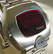
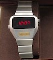
Digital watch collectors usually name the Pulsar P1 as the most sought after LED watch. Together with the solar powered Synchronar MK I it was the first digital watch which has been produced in series. The Pulsar watches were available on the market in spring of 1972.
When the 18 karat solid gold P1 was launched the watch was delivered with a module manufactured by Electro Data of Garland, Texas. This company was founded in 1966 and probably started work on digital timepieces at the very beginning. It was 1968 when Electro Data contracted to Hamilton with the development of a digital watch module. As a result a first prototype could be released in 1969, today known as the 44 chip module. It had six digits which were basically custom versions of Hewlett Packard’s first series 5082-7000 LED display.
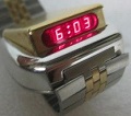
A 2nd generation module of Electro Data also came with six digits, however their package was much smaller and the manufacturer remains unknown. The number of chips used on this module was reduced from 44 to 25 and it was supposed to fulfil the requirements of the Pulsar marketing department: The module was expected to be accurate to within 60 seconds a year and Hamilton estimated a lifelong flawless operation as there were no moving parts which could abrade.
When the first P1 watches were sold it turned out that the 25 chip module could not meet any of its expectations as all modules stopped working during the first months of use. For this reason most of the watches have been returned under warranty to the Pulsar facility in Lancaster, Pennsylvania where they were swapped against a later circuit developed at RCA. This modern one chip four digit circuit – technically far ahead of the 25 chip module - became standard with the introduction of the Pulsar P2.
In the rare event of a new P1 sale serious collectors are initially checking the watch for its module. It is likely that most but not all P1 owners returned their watches upon the big call back. But are there chances for new appearing watches with an early 25 chip six digit module? Or as a fellow dwf.cc member put it “Which raises the interesting possibility that the Holiest Grail of all might be to find a pissed off 1972 owner of a dead P1 in the bottom of a draw, that did not get sent back and still has the 6 digit module”. But let us have a look on these early type modules and estimate the chances for a running specimen in 2013.
Today about six early Electro Data modules are known to exist in collectors’ hands but none of them are working. When my P1 arrived which was bought for a single reason - to try a repair attempt - I was astonished in that the watch proved to be unopened. I did not put batteries in the watch at this time because I was sure the previous owner already did that without success. I immediately stored the watch in a drawer until I did any further work as I was just too busy with my job plus the repair of customer LED watches.
When I took the P1 out of the drawer again after about two weeks I opened the battery compartments with the little P shaped magnet. Usually the magnet should be sitting in the clasp, but for various reasons the magnets are often missing. When the battery covers were removed, I could not find any signs of damage caused by the batteries indicated by corrected battery terminals for example. And even the batteries were removed. I looked at the two battery springs which had ugly soldering spots on them, especially where the powering wires between batteries and board are connected.
As mentioned before I was not expecting a working watch. Instead I was hoping for a clean board so that a repair attempt would make sense and regarding my latest purchase it seemed that I was lucky. At the early beginning of a repair it is always a good idea to check the current flow of a non - working digital watch. You can say within seconds if the module is worth a repair or not. First tests with my self made module tester connected to the battery springs showed a current flow of 21mA without any display activity. This current flow is way too high for a flawless working module. Now it was clear that plenty of time would go into the analysis and the repair of the movement where I could expect more than a weak solder joint. The good part of the story is that the module has been built in discrete circuits and no microcontroller has been used. So I consider a repair of the module as generally possible.
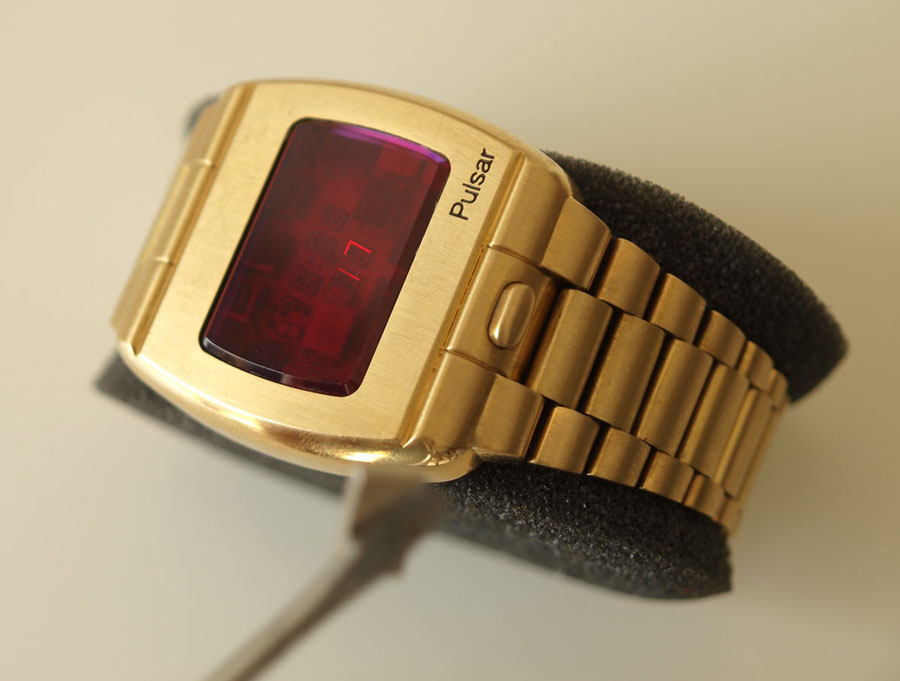
Instead of the assumption that the case and the back of the P1 were soldered together my watch was glued. The same red – brownish epoxy which can be found to attach the red crystal to the watch case has been taken. The overall appearance of the case was good as there were no deep scratches on the surface and bracelet. Moreover the red glass is in excellent condition. I never asked for high resolution pictures of the case before I finally purchased the watch because I was interested in the module mainly. So the condition of the watch was another positive aspect next to the missing signs of battery leakage. I then counted a number of 21 bracelet links. The watch has been originally delivered with 22 links so just one is missing. Still the bracelet is too long to fit my tiny wrist, so that I will shorten the bracelet again with one significant difference: The links will be stored with the watch.
When I found the time to do further work on the watch its back had to be removed. Surprisingly there was no instruction in the www available, so I thought to get some tips of other collectors. In the end I decided to use two coffee cups on the bracelet with a towel in between so that the links would not be damaged. With these cups I could held the watch down while pulling on the back and applying heat on the sealing. Because of the soft case back made of 18 k gold mechanical tools would probably cause damage on the case so one has to be very careful during the opening process. It turned out to be a good idea to pull a tiny rope trough the battery holes so that you can pull from a distance instead of dealing with the hot case directly. Four hands will be helpful so a 2nd person is recommended. When applying heat (A standard Bosch heat gun just came handy) the back came off easily following the described method. Next the module holder was glued with the same epoxy that was used to seal the case, so eventually you have to repeat the procedure. Still I was surprised that nobody tried to open the watch prior to my repair attempt.
But now it was time to look at the module: There are golden traces on a cream-white ceramic circuit board housing 25 chips, each with a corresponding letter on the top of their ceramic covers and six tiny digits which I have not seen on other watches or technical equipment. Peter Formanek, a watch collector and seller from Canada once told me that the chips on the board are unlikely to fail, but it is the connection between the pads of the ceramic carrier and the circuit board which cause malfunctions. When I took the module off the case one “A” marked ceramic carrier immediately came off although I had not touched it. When I picked up the carrier I could see the whole mess: The chip under the ceramic carrier is covered with some kind of black sealant – probably a protection for the tiny gold wire bonds which connect the chip with the pads of the carrier.
A wire bond is a method to connect two very tiny pads with a super thin gold or aluminium wire with the use of ultrasonic sound. With changing temperatures, the black sealant covering the chip expands – much more than the ceramic carrier - and finally lifts off the whole carrier with chip. Of course the corresponding bond connections become destroyed. Summarized a repair person needs to have full access to a wire bonding machine as there is no other way to install the broken connections again.
It was time to switch my bonder on and start to replace broken bond connections. Finally I managed to replace the wire bonds on the circuit board. However I was not able to perform this work on the display as I could not get the wire bond to stick on the corresponding pad. These pads were just too corroded and in addition were covered by a film of solder flux which was probably applied after the bonding process.
My six digit display has been double wire bonded which means that two wire bonds are connected to one segment for reliability. You can test the display using the leads of a standard digital multimeter set to diode testing. Attach the black lead to ground and hold the red lead on the trace for the corresponding digit. The display then should light up without being destroyed through high current flow. 34 of a total of 37 bars (5x 7 segment display + 2 segments for the first “1” display) of all digits and the two dots to divide hour and minute display lighted up. The middle bar of the lower left digit which makes an 8 out of a 0 and the two upper left bars from the 2nd upper and second lower digit did not because of broken wire bonds.
Because I had no idea how to proceed with the wire bonding problem I started to check the circuit. From a modern view the 25 chip circuit is easy – built: You start with the quartz and between the display and the quartz there are only counters or divider chips to count the time and prepare the display output in binary code. To set minutes or seconds, you just bypass a timing counter so that the values increase faster.
Just before the display you can find five binary to seven segment decoders with display drivers at the output. Five were used to drive the anodes of the display (the display bars) which include all chips marked with an “A”. The drivers were needed because the CMOS decoder chips cannot drive the display itself as the current flow would be too high. Then you have five cathode drivers to drive the segments. These are the chips marked with a “K”. The first “half” digit and the colon was driven by the chip with the number “1”, so this chip is both housing an anode and a cathode driver. This means that the circuit of the E/D module is slightly different from what was filed as Patent 3,789,601 from Feb. 5 1974. In this patent from Mr. Bergey, the seconds display is tied toghether with the first and second digit of the minute display which has not been done on the 25 chip module.
The light sensors, basically resistors regulate the current flow to the display drivers so that the display brightness is higher in a brighter environment. More light means that the resistance of the sensor is lower, so you have more current flow to the display. Interesting is, that you can find quite a lot of ceramic capacitors on the module which avoid intermittent problems at the circuit.
When I finally managed to get the circuit in fully working order (after about a year!) I made a few calls and was successful in that I found Fraunhofer Institut in Berlin. They agreed to help me with the watch module. The Fraunhofer Institut is an R&D organization operated by the german government. They do research and development work for the industry and are known for clever people and their excellent machinery. The trick to re-bond the display was to remove the old, broken bond and apply a new bond exactly on its place which was protected all the time through the bond base of the old bond. I neither had the machine to remove the old bond nor the knowledge how to operate one. I drove to Berlin to deliver the module and picked it up in person a few weeks later. Back home I immediately tested it and was quite proud to have a working 6 digit module in my hands. My high spirits changed into bad temper when I realized that the magnet strength of the original P1 button in the watch case was too weak to activate any kind of reed switch I had. No doubt I have plenty of different switches in my stock, but nothing matched the case button strenght. So the watch lay around for another month until I had an idea how to repair the switch. I heated up my kitchen oven up to 200 °C and put the case in. Be careful and remove the glass first! After about 10 minutes, the watch button came out easily. Because I did not want to damage the old button I glued a tiny magnet with a diameter of 1,5mm and a thickness of just 0,5mm on top of the old magnet. When the glue dried I carefully soldered the button with the back plate in the case again. You neither can see nor feel that this button has ever been repaired. Now it was time to assemble everything. I was so excited that I forgot to take pictures of the module. The case has been closed with 4 little glue spots until I receive the coloured epoxy to replicate the original technique.
Summarized I am sure that E/D knew their modules would fail. There are just too many design flaws such as the sealant, the battery connectors or the lack of clipping diodes at each chip. As a (mechnical) engineer myself I usually have a feeling if a construction is good for a few months of operation or if the assembly literally works forever. However we must keep in mind that Electro Data dealt with new technology as a relative small company and without an endless amount of time and money. So there is enough reason for the Electro Data engineers to be proud of building the first digital watch module in series. And these hand - build early modules are nicer than any mechanical movement – wouldn´t you agree?

Digital watch collectors usually name the Pulsar P1 as the most sought after LED watch. Together with the solar powered Synchronar MK I it was the first digital watch which has been produced in series. The Pulsar watches were available on the market in spring of 1972.
When the 18 karat solid gold P1 was launched the watch was delivered with a module manufactured by Electro Data of Garland, Texas. This company was founded in 1966 and probably started work on digital timepieces at the very beginning. It was 1968 when Electro Data contracted to Hamilton with the development of a digital watch module. As a result a first prototype could be released in 1969, today known as the 44 chip module. It had six digits which were basically custom versions of Hewlett Packard’s first series 5082-7000 LED display.
A 2nd generation module of Electro Data also came with six digits, however their package was much smaller and the manufacturer remains unknown. The number of chips used on this module was reduced from 44 to 25 and it was supposed to fulfil the requirements of the Pulsar marketing department: The module was expected to be accurate to within 60 seconds a year and Hamilton estimated a lifelong flawless operation as there were no moving parts which could abrade.
When the first P1 watches were sold it turned out that the 25 chip module could not meet any of its expectations as all modules stopped working during the first months of use. For this reason most of the watches have been returned under warranty to the Pulsar facility in Lancaster, Pennsylvania where they were swapped against a later circuit developed at RCA. This modern one chip four digit circuit – technically far ahead of the 25 chip module - became standard with the introduction of the Pulsar P2.
In the rare event of a new P1 sale serious collectors are initially checking the watch for its module. It is likely that most but not all P1 owners returned their watches upon the big call back. But are there chances for new appearing watches with an early 25 chip six digit module? Or as a fellow dwf.cc member put it “Which raises the interesting possibility that the Holiest Grail of all might be to find a pissed off 1972 owner of a dead P1 in the bottom of a draw, that did not get sent back and still has the 6 digit module”. But let us have a look on these early type modules and estimate the chances for a running specimen in 2013.
Today about six early Electro Data modules are known to exist in collectors’ hands but none of them are working. When my P1 arrived which was bought for a single reason - to try a repair attempt - I was astonished in that the watch proved to be unopened. I did not put batteries in the watch at this time because I was sure the previous owner already did that without success. I immediately stored the watch in a drawer until I did any further work as I was just too busy with my job plus the repair of customer LED watches.
When I took the P1 out of the drawer again after about two weeks I opened the battery compartments with the little P shaped magnet. Usually the magnet should be sitting in the clasp, but for various reasons the magnets are often missing. When the battery covers were removed, I could not find any signs of damage caused by the batteries indicated by corrected battery terminals for example. And even the batteries were removed. I looked at the two battery springs which had ugly soldering spots on them, especially where the powering wires between batteries and board are connected.
As mentioned before I was not expecting a working watch. Instead I was hoping for a clean board so that a repair attempt would make sense and regarding my latest purchase it seemed that I was lucky. At the early beginning of a repair it is always a good idea to check the current flow of a non - working digital watch. You can say within seconds if the module is worth a repair or not. First tests with my self made module tester connected to the battery springs showed a current flow of 21mA without any display activity. This current flow is way too high for a flawless working module. Now it was clear that plenty of time would go into the analysis and the repair of the movement where I could expect more than a weak solder joint. The good part of the story is that the module has been built in discrete circuits and no microcontroller has been used. So I consider a repair of the module as generally possible.
Instead of the assumption that the case and the back of the P1 were soldered together my watch was glued. The same red – brownish epoxy which can be found to attach the red crystal to the watch case has been taken. The overall appearance of the case was good as there were no deep scratches on the surface and bracelet. Moreover the red glass is in excellent condition. I never asked for high resolution pictures of the case before I finally purchased the watch because I was interested in the module mainly. So the condition of the watch was another positive aspect next to the missing signs of battery leakage. I then counted a number of 21 bracelet links. The watch has been originally delivered with 22 links so just one is missing. Still the bracelet is too long to fit my tiny wrist, so that I will shorten the bracelet again with one significant difference: The links will be stored with the watch.
When I found the time to do further work on the watch its back had to be removed. Surprisingly there was no instruction in the www available, so I thought to get some tips of other collectors. In the end I decided to use two coffee cups on the bracelet with a towel in between so that the links would not be damaged. With these cups I could held the watch down while pulling on the back and applying heat on the sealing. Because of the soft case back made of 18 k gold mechanical tools would probably cause damage on the case so one has to be very careful during the opening process. It turned out to be a good idea to pull a tiny rope trough the battery holes so that you can pull from a distance instead of dealing with the hot case directly. Four hands will be helpful so a 2nd person is recommended. When applying heat (A standard Bosch heat gun just came handy) the back came off easily following the described method. Next the module holder was glued with the same epoxy that was used to seal the case, so eventually you have to repeat the procedure. Still I was surprised that nobody tried to open the watch prior to my repair attempt.
But now it was time to look at the module: There are golden traces on a cream-white ceramic circuit board housing 25 chips, each with a corresponding letter on the top of their ceramic covers and six tiny digits which I have not seen on other watches or technical equipment. Peter Formanek, a watch collector and seller from Canada once told me that the chips on the board are unlikely to fail, but it is the connection between the pads of the ceramic carrier and the circuit board which cause malfunctions. When I took the module off the case one “A” marked ceramic carrier immediately came off although I had not touched it. When I picked up the carrier I could see the whole mess: The chip under the ceramic carrier is covered with some kind of black sealant – probably a protection for the tiny gold wire bonds which connect the chip with the pads of the carrier.
A wire bond is a method to connect two very tiny pads with a super thin gold or aluminium wire with the use of ultrasonic sound. With changing temperatures, the black sealant covering the chip expands – much more than the ceramic carrier - and finally lifts off the whole carrier with chip. Of course the corresponding bond connections become destroyed. Summarized a repair person needs to have full access to a wire bonding machine as there is no other way to install the broken connections again.
It was time to switch my bonder on and start to replace broken bond connections. Finally I managed to replace the wire bonds on the circuit board. However I was not able to perform this work on the display as I could not get the wire bond to stick on the corresponding pad. These pads were just too corroded and in addition were covered by a film of solder flux which was probably applied after the bonding process.
My six digit display has been double wire bonded which means that two wire bonds are connected to one segment for reliability. You can test the display using the leads of a standard digital multimeter set to diode testing. Attach the black lead to ground and hold the red lead on the trace for the corresponding digit. The display then should light up without being destroyed through high current flow. 34 of a total of 37 bars (5x 7 segment display + 2 segments for the first “1” display) of all digits and the two dots to divide hour and minute display lighted up. The middle bar of the lower left digit which makes an 8 out of a 0 and the two upper left bars from the 2nd upper and second lower digit did not because of broken wire bonds.
Because I had no idea how to proceed with the wire bonding problem I started to check the circuit. From a modern view the 25 chip circuit is easy – built: You start with the quartz and between the display and the quartz there are only counters or divider chips to count the time and prepare the display output in binary code. To set minutes or seconds, you just bypass a timing counter so that the values increase faster.
Just before the display you can find five binary to seven segment decoders with display drivers at the output. Five were used to drive the anodes of the display (the display bars) which include all chips marked with an “A”. The drivers were needed because the CMOS decoder chips cannot drive the display itself as the current flow would be too high. Then you have five cathode drivers to drive the segments. These are the chips marked with a “K”. The first “half” digit and the colon was driven by the chip with the number “1”, so this chip is both housing an anode and a cathode driver. This means that the circuit of the E/D module is slightly different from what was filed as Patent 3,789,601 from Feb. 5 1974. In this patent from Mr. Bergey, the seconds display is tied toghether with the first and second digit of the minute display which has not been done on the 25 chip module.
The light sensors, basically resistors regulate the current flow to the display drivers so that the display brightness is higher in a brighter environment. More light means that the resistance of the sensor is lower, so you have more current flow to the display. Interesting is, that you can find quite a lot of ceramic capacitors on the module which avoid intermittent problems at the circuit.
When I finally managed to get the circuit in fully working order (after about a year!) I made a few calls and was successful in that I found Fraunhofer Institut in Berlin. They agreed to help me with the watch module. The Fraunhofer Institut is an R&D organization operated by the german government. They do research and development work for the industry and are known for clever people and their excellent machinery. The trick to re-bond the display was to remove the old, broken bond and apply a new bond exactly on its place which was protected all the time through the bond base of the old bond. I neither had the machine to remove the old bond nor the knowledge how to operate one. I drove to Berlin to deliver the module and picked it up in person a few weeks later. Back home I immediately tested it and was quite proud to have a working 6 digit module in my hands. My high spirits changed into bad temper when I realized that the magnet strength of the original P1 button in the watch case was too weak to activate any kind of reed switch I had. No doubt I have plenty of different switches in my stock, but nothing matched the case button strenght. So the watch lay around for another month until I had an idea how to repair the switch. I heated up my kitchen oven up to 200 °C and put the case in. Be careful and remove the glass first! After about 10 minutes, the watch button came out easily. Because I did not want to damage the old button I glued a tiny magnet with a diameter of 1,5mm and a thickness of just 0,5mm on top of the old magnet. When the glue dried I carefully soldered the button with the back plate in the case again. You neither can see nor feel that this button has ever been repaired. Now it was time to assemble everything. I was so excited that I forgot to take pictures of the module. The case has been closed with 4 little glue spots until I receive the coloured epoxy to replicate the original technique.
Summarized I am sure that E/D knew their modules would fail. There are just too many design flaws such as the sealant, the battery connectors or the lack of clipping diodes at each chip. As a (mechnical) engineer myself I usually have a feeling if a construction is good for a few months of operation or if the assembly literally works forever. However we must keep in mind that Electro Data dealt with new technology as a relative small company and without an endless amount of time and money. So there is enough reason for the Electro Data engineers to be proud of building the first digital watch module in series. And these hand - build early modules are nicer than any mechanical movement – wouldn´t you agree?